|
|
 |
|
|
|
|
|
3-D Presentation of Calibration DATA of a Perimetry Eye Tracker
Digital Journal of Ophthalmology 1997
Volume 3, Number 1
February 1, 1997
|
Printer Friendly
|
|
|
|
|
| Abstract | Objective
A calibration method for eye movements monitoring in standard and objective static perimeters is described. Current static perimeters require the subjects to maintain steady fixation during the entire examination. By implementing eye tracking methods adopted for perimetry, automatic fixation monitoring is possible during perimetrical test. Successful fixation monitoring allows conditional eye movements. An important issue in designing a fixation monitoring unit is the method of initial eye tracker calibration. The aim of this study is to demonstrate an alternative way to present the eye tracker calibration DATA in a three dimensional coordinate system. The resulting figure allows precise and fast calibration DATA assessment. The calibration method is based on an analysis of the distance between the images of the corneal reflection and the pupil center for calibration points at specific locations. The method provides an accuracy of 1deg. in calculating the fixation point for +/- 20 deg. eccentricities of the line-of-sight relative to the center of the perimeter by using 8 calibration points and could be expanded to any other view field by using more calibration points. The calibration procedure can be completed in under 1 minute. The required time depends on the patient's ability to concentrate. The model is subject specific and once calculated it can be used in multiple recording sessions. Based on the perimeter's polar coordinate system this model is particularly suitable for implementation in perimetry, however, it can easily be adopted in eye testing equipment with different setups.Keywords
eye tracker, perimeter, calibration | | | Introduction | The alignment of the coordinate system of the retina with that of the perimeter is one of the prerequisites for examining the human retina by means of stimulation of small regions of the retina by small visual targets. This is usually achieved by HAVING the patient fixate a pre-defined point on the perimeter's hemisphere [6], [7] but this can fatigue the patient during lengthy perimetrical examinations.
The perimeter, CAMEC, offers an interesting solution: the subject makes controlled eye movements to a moving target of regard [15]. This is less tiring, and maintains the subject's interest and gaze fixation during the entire test. The method, however, cannot be implemented with subjects who do not or cannot fixate the target as required, and therefore cannot be implemented in static perimeters. This problem could be avoided by integrating eye tracking units INTO modern perimeters.
To our knowledge, there aren't any commercially available hemisphere perimetrical units which allow for free eye movements by HAVING the fixation point coordinates calculated on-line. The main difficulties of implementing eye tracking systems in standard or VEP based perimeters arise FROM the following specific requirements:
on-line operation;
accuracy in calculating the fixation point (1 - 1.5 deg.);
efficiency under low illumination (max. 10 cd/m2);
no head-mounted equipment, no equipment obstructing the visual field;
minimal number of the calibration points to avoid tiring the patient.
short calibration procedure (less than a minute).
no invasive methods for eye movement detection
A GROUP of methods meeting these requirements are the camera based eye tracking methods. They vary FROM simple visual comparison and manual measurement of the pupil's position to more complex methods based on composite video on-line analysis. The most common procedure for calculating gaze direction uses the analysis of the position of a single corneal reflection image with regard to the pupil's centre image [3], [11], [14], [17], [18]. Essential for all these methods is the calibration of the tracking unit to the gaze movement of the subject. Different calibration procedures are used in eye tracking and these vary depending on the aims of the system and the algorithm for interpreting the calibration data. Examples vary FROM a look-up-table which contains information about the eye position for every symbol in the area of interest such as the keys of a gaze controlled typewriter [1] to a polynomial least squares approach to calibration using 28 calibration points in a rectangular coordinate system for tracking a pilot's gaze within a restricted confines of the cockpit [14]. The polynomial least squares method is the most common calibration method. It is based on compensation of the nonlinearities in the gaze movement for given directions by calculating coefficients in a system of polynomial equations [3]. Although it is functional, the number of coefficients does not give us any visual rendition of the calibration DATA so that it is difficult to obtain direct feedback about whether the calibration DATA are sufficient for use in the intended application.
This paper describes a calibration method which could be easily implemented in the development of an eye tracker for the commercially available perimeters and offers three dimensional visual rendition of the calibration data. As all further explanations are referred to the images of the pupil and the corneal reflection, later in the text the expressions "pupil centre" and "corneal reflection centre" will be used instead of "entrance pupil centre image" and "corneal reflection centre image". | | | Materials and Methods | The perimeter system expresses the coordinates of the stimuli on the surface of the perimeter's hemisphere in polar coordinates - eccentricity (alpha ') and meridional direction (phi ') (Figure 1). For given coordinates of the head, the hemisphere-related coordinates of the gaze fixation point alpha' and phi' can be calculated. The corneal reflection to pupil centre distance principle was selected as a methodological basis for eye movement detection. According to this principle, an eye movement can be defined in terms of the coordinates of the pupil centre (PC) in relation to the corneal reflection centre (CRC) caused by a light source FROM the perimeter's screen with known coordinates. We assume the distance between the corneal reflection centre and the centre of the pupil to be a vector (CRP-vector). The length of this vector (CRC_PC) and the angle . between it and a predefined axis drawn through the corneal reflection centre are the two parameters that completely characterize the vector (Figure 2). The length of the CRP-vector and its meridional direction, phi , are directly related to the particular fixation point coordinates, eccentricity alpha ' and meridional direction phi ', within the perimeter stimuli area. This relation remains constant over time for a given eye and may depend on the individual location of the area being used to direct gaze, probably the region of highest acuity, the fovea for most subjects. If necessary, changes of the retinal coordinates of the area used to direct gaze can be taken in consideration by updating the calibration data. This means that one calibration can usually be used in multiple record sessions, expediting parametric evaluation.
A nonlinearity exists between the parameters of the CRP-vector (phi , CRC_PC) and the spherical coordinates of the fixation point (meridional direction phi ', eccentricity alpha '). It is caused by the following factors [14], [17], [18]:
varying radii of the curvature of the cornea;
decentralizing of the inter-axes space in which the eye rotation centre is situated, with respect to the geometrical eye centre.
the angular offset between the eye's optic and visual axes
individual parameters of the eye's optics
The aim of the following analysis is to develop a calibration method to take this nonlinearity INTO consideration. The output of the method has to present the calibration DATA in a way appropriate for easy implementation in a programming language as well as for visual rendition. The method is "self- contained". Neither geometrical eye models nor any other parameters except these of the CRP-vector were used in developing the calibration method.
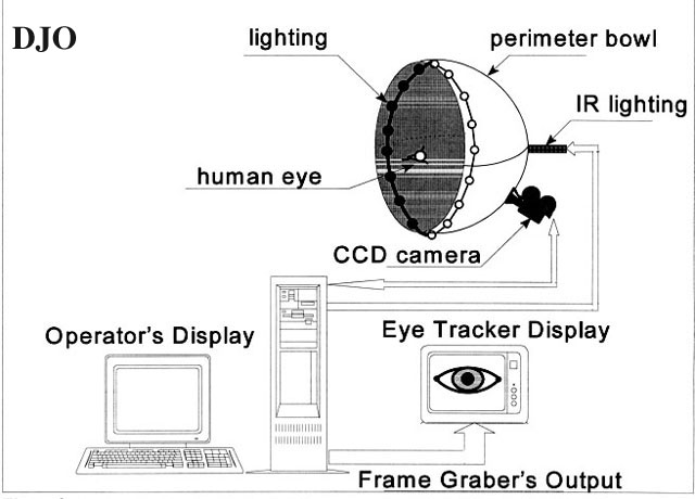
The hardware setup we used to perform the tests was a RODENSTOCK "Peristat-433" perimeter with a built-in SONY-XC-77CE CCD camera (512x512 square pixels) and a LFS-AT/486 frame grabber FROM Leutron Vision (Figure 3). The CCD-camera was calibrated to measure distance at the plane of the eye for the given hardware configuration. Parallax due to camera offset was taken INTO consideration. An IBM-PC486 was used as a host computer. The software for image recognition, calibration and calculation of the fixation point coordinates was written by the authors in C++. The appearance of artefacts in the image of the eye (shadows FROM the eyelids, reflections FROM the tear film etc.) was minimized by using adjustable diffuse illumination inside the perimeter. In addition, a nonlinear Input Look Up TABLE for the camera was used for additional on-line optimization of the image of the eye. Noise resistant methods for detection of the pupil centre and corneal reflection centre were implemented. The details of this calculations are not germane to the calibration procedure described here.
Coordinate system
See Figure 4
To present the relation between the polar coordinates of the fixation point and the corresponding parameters of the CRP-vector, a 3D orthogonal coordinate system was defined (Figure 4). The vertical z-axis is used for representing the changes in the length of the vector (CRC_PC) in mm for different fixation points. The centre of the 3D coordinate system expresses the zero point of the hemisphere polar coordinate system. The x/y plane represents the polar coordinate system of the perimeter's screen for displaying the stimuli. Each calibration or fixation point FROM the perimeter's hemisphere can be defined in the x/y plane by its eccentricity alpha ' and meridional direction phi '. In addition, the phi coordinate of the CRP-vector is also presented in an orthogonal coordinate system. This allows the DATA for the meridional directions of the CRP vector to be presented in the x/y plane as well. To do this, however, it is necessary to align the coordinate system for representing the CRP vector to the 2D coordinate system of the x/y plane. This can be achieved by aligning the quadrant of the CRP vector coordinate system in which the vector is situated when the eye is fixating points FROM the first perimeter hemisphere quadrant with the first quadrant of the x/y plane. This alignment will be different for different configurations of recording equipment, depending on whether the camera is recording a mirror image of the eye or monitoring the eye directly. In case of direct monitoring, for example, because of the known mirror image effect, the second quadrant of the coordinate system of the CRP-vector corresponds to the first quadrant of the space coordinate system (swapping Left to Right).
This way each position of the CRP-vector can be redefined in the 3D coordinate system by the length of the vector and its meridional direction. Therefore, within such a coordinate system, the nonlinearities between phi ' and phi (phi-nonlinearity) as well as between the eccentricity of the fixation point and the corresponding value of the length of the CRP-vector (alpha-nonlinearity) can be represented simultaneously.
Analysis of the phi- and alpha-nonlinearity
The function of the phi-nonlinearity F(phi, alpha') for one particular hemisphere meridian can be experimentally calculated by recording the value of the angle phi of the CRP-vector during the gaze fixations at a series of successive points on the same hemisphere meridian. Due to physiological peculiarities, this function does not coincide with the meridian and monotonically increases throughout the whole gaze movement. This function describes the individual characteristics of the fixation positions along only one particular hemisphere meridian.
In the same way, the function of the alpha-nonlinearity F(CRC_PC,alpha', phi) for one particular perimeter meridian can be experimentally calculated by recording the length of the CRP-vector during gaze fixations at a series of points which belong to this hemisphere meridian (phi ' = constant). This function will also monotonically increase along the same hemisphere meridian. The projection of every function F I (CRC_PC, alpha', phi) in the x/y-plane coincides with the respective function of the phi- nonlinearity calculated for this meridian.
Therefore, if the number of calibration points in one predefined meridional direction is infinite, both of these functions would contain the complete information about the - and .-nonlinearities of the gaze movement along that given meridian. Since the eyes always take up the same horizontal and vertical position when viewing a given target, the principle of the invariant eye ball position for one and the same fixation point is valid for these functions. These functions are totally individual and cannot characterize the movement of any other subject's eye. Anatomical and physiological factors cause the profile of the functions F(phi, alpha') and F(CRC_PC, alpha', phi) to be constant throughout a given perimetrical examination and across sessions with the same perimeter.
For a given number N of calibration meridians, the functions F I (CRC_PC,alpha ', phi) could be represented within the 3D coordinate system defined above. Since each of the functions is monotonically increasing, the resulting 3D calibration surface displays a concave geometrical form which could be described as the calibration surface for a given subject. For infinite number calibration points and if there is no calculation error in the CRP-vector coordinates, the calibration DATA represent the ideal calibration surface for a given subject.
This model is applicable to any gaze direction in the perimeter as long as the pupil's centre can be detected. The number of calibration points needed will depend on how far INTO the periphery one wishes to record. Because of the different radii of the sclera and of the cornea, theoretically the number of calibration points per calibration meridian is at least M + 1 + Q in which: M is the number of calibration eccentricities per meridian for approximation of the alpha- and phi-nonlinearities when the CR is inside the cornea; at least one calibration point per meridian is necessary to collect calibration DATA for both functions on the outline of the cornea; Q is the number of eccentricities per meridian which are necessary when calibrating outside the cornea.
A series of tests proved that for fixation point eccentricities smaller than 20·, the functions FI(phi, alpha') and FI(CRC_PC, alpha', phi) are almost linear. It is also known that for greater eccentricities, a head movement occurs simultaneously with the eye movement. As the head is restrained in the perimetry task, and on line image processing for detection of the pupil and corneal reflection textures is less accurate under larger angles, we decided to test the calibration model for +/- 20 deg. eccentricities. We decided to use linear approximation to these functions. The crossing point with the functions corresponds to a given calibration eccentricity for each calibration meridian. A number of measurement sessions led to the conclusion that the calibration points should be defined at eccentricity alpha calibration = 15 deg. The minimum number of calibration meridians is eight: four meridians for examining of the eye movements in horizontal and vertical directions and four meridians for examining of the oblique gaze movement which we decided to define at phi '= 45·deg, 135·deg, 225·deg, 315·deg. The following calibration map of a total of eight points resulted FROM this procedure (Figure 5). According to the analysis of the alpha- and phi-nonlinearities, the resulting DATA after the calibration should correspond to a concave surface defined within the 3D coordinate system by the eight linear functions for approximation of the alpha-nonlinearity (alpha-functions). The projection of these functions in the x/y-plane corresponds to the linear functions for approximation of the phi-nonlinearity (phi-functions). This way each point of the calibration surface corresponds to particular coordinates of the CRP-vector. If its coordinates are measured, the coordinates of the corresponding fixation point in the x/y plane of the 3D coordinate system can be calculated. The mathematical methods for this calculation depend on the method for approximation of the - and .-nonlinearities. | |
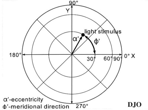
Figure 1
Perimeter hemisphere coordinate system
|
|

Figure 2
The CRP-vector. The center of the coordinate system coincides with the corneal reflection centre.
|
|
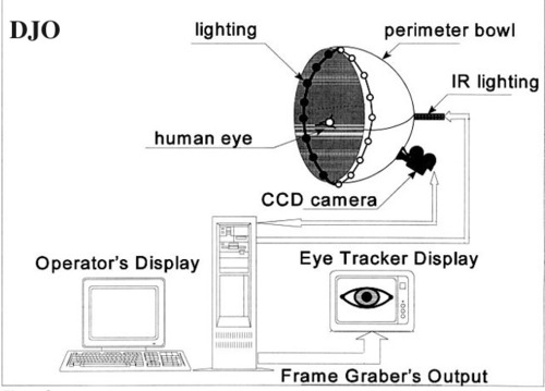
Figure 3
Testing system hardware.
|
|
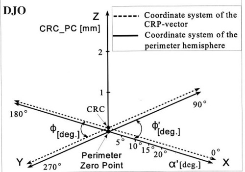
Figure 4
Coordinate system for calibration DATA representation.
|
|
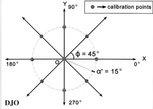
Figure 5
Positioning of the calibration points on the perimeter hemisphere.
|
|
| Results | The test studies to derive functions of the - and .-nonlinearities were performed on six trained subjects. During the tests those functions were calculated by measuring the CRP-vector coordinates for calibration points alpha calibration = 10·deg, 15·deg, 20·deg, 25·deg and phi calibration = 0·deg, 45·deg, 90·deg, 135 deg, 180·deg, 225·deg, 270·deg and 315·deg. The profile of the calculated functions confirmed the theoretically expected trend for the alpha- as well as for the phi-nonlinearity. To SHOW the individual profile of these functions, representative examples are given in Figure 6 and Figure 7. A representative example of a correct calibration surface is shown in Figure 8. The absence or presence of spikes on this surface gives the operator feedback about the applicability of the calibration. The feasibility of the method was finally tested by calibrating the gaze tracking unit by means only of the suggested eight calibration points. For each calibration meridian the calibration functions for the alpha- and the phi-nonlinearity were calculated by linear approximation. We tested how the system calculates the fixation point coordinates by HAVING subjects fixate test points with known coordinates. Each subject was tested several times but the calibration was performed only once, before the first test. The calibration time varied between 20 and 45 sec and depended mostly on the subject's concentration. The time span between the test sessions varied FROM a couple of minutes to several days.
Before every new test the calibration DATA was automatically retrieved FROM the initial calibration procedure. Each time the offset of the system was calibrated by only one-point calibration at the centre of the perimeter hemisphere coordinate system. The analysis of how the system calculates the coordinates of the fixation point was based on the DATA FROM 104 measurements with 6 subjects for 15 test points inside the calibration area.
The following deviations of the calculated target point FROM the real target point were observed:
standard deviation while calculating the alpha'-coordinate of the test point delta alpha standard = 1.08 deg
standard deviation while calculating the phi'-coordinate of the test point delta phi standard = 2.18·deg
In 78.9% of the cases the error in calculating the eccentricity of the fixation point was less than 1·deg. In 25% of the cases the error in calculating the meridional direction of the fixation point for oblique gaze movements was less than 1·deg and 41.6% of the measurements in the same case were with accuracy better than 1.5·deg. In the cases of calculating the meridional direction for the major horizontal and vertical axes the accuracy was better than 1·deg in 85.3% of the cases. Values for the outliers (those with a value greater than 1·deg) in both distributions are dependent on the particular quality of the picture, the subjects' concentration and the method chosen for calculating the centres of the pupil and the corneal reflection.
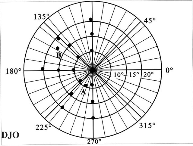
An example of how the software calculates and represents the coordinates of the different pre-defined points of regard is shown in Figure 9. The meridians SHOW the meridional direction phi', in steps of 10 deg.; the concentric circumferences SHOW the eccentricity alpha' for 10, 15 and 20 deg. The black points represent the points of regard calculated by the eye tracker. The mouse allows the operator to read their coordinates with regard to the coordinates of the perimeter's hemisphere. In on-line mode, the coordinates of the fixation point are given in an additional window. The calibration procedure can be controlled directly by the options given on the screen. The results FROM the test and the calibration DATA can be stored in a subject oriented library. There is an option in the software for an on-line calibration of the input look-up-table of the CCD-camera.
By the calculation of the coordinates of the test points the following errors could be observed:
- the image-processing was not optimal (point A alpha' = 10·, phi' = 246·deg). As the freeze mode image analysis proved, this error was caused by incorrect detection of the pupil's centre, due to image disturbances around the eye lashes. After adjusting the illumination, the target point (alpha' = 10·deg, phi' = 270·deg) was successfully detected;
- low patient's concentration (point B alpha' = 17.8·, phi ' = 143·deg). The loss of concentration of the patient was deliberately caused by prolonging the fixation duration. After a short relaxation the same test was repeated within a maximum fixation duration of 2 seconds. The target point alpha' = 20·, phi' = 135· deg was successfully detected. | |
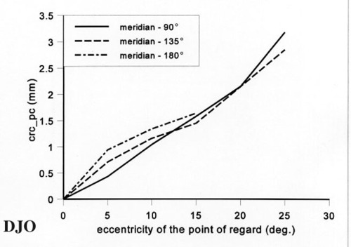
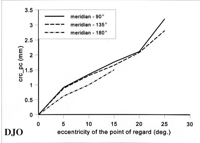
Figure 6
The function F1(CRC_PC, alpha', phi) for meridian 90 deg, 135 deg and 180 deg for representative subject 1.
|
|

Figure 7
The function F1 (CRC_PC, alpha ', phi) for meridians 90 deg, 135 deg and 180 deg for representative subject 2.
|
|
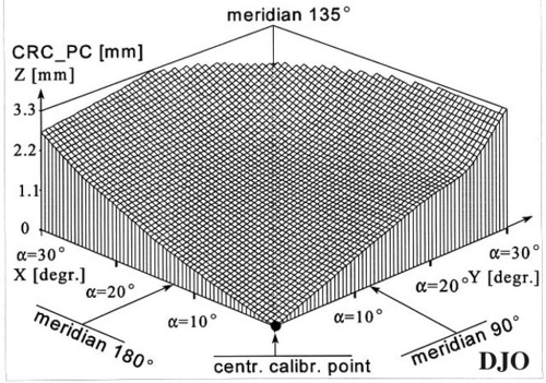
Figure 8
Part of the 3D calibration DATA between the 90 deg and 180 deg meridian for representative subject 2.
|
|

Figure 9
A hemisphere map. The black points represent the calculated points of regard. Predefined points at alpha ' = 10 deg, 15 deg, 20 deg and phi ' = 90 deg, 135 deg, 180 deg, 225 deg, 270 deg.
|
|
| Discussion | The described calibration algorithm of the gaze tracking unit is based on a 3D presentation of the individual characteristics of the horizontal, vertical and oblique gaze movements. The advantage of this model is that it represents in one figure, which is easy for immediate visual perception, the non-linearities between the eccentricity and the meridional direction of the fixation point and their corresponding values of the length and meridional direction of the CRP-vector. The coordinate system of the 3D surface results directly FROM the perimeter's polar coordinate system and is therefore very suitable for implementation in perimeter eye trackers. The calculated calibration surface is individual and remains unchanged over long periods of time as long as there is no disease. This makes repeated calibration procedures superfluous so that perimetry sessions go more smoothly for the subject. If the eye images during calibration are saved, an off-line analysis is also possible. This will eliminate even small errors caused by image processing. In this case the repeatability of the calibration DATA depends mostly on the patient's capability for concentration. It is to be expected that for patients with concentration difficulties this problem is easily dealt with by performing multiple calibration sessions.
The calibration DATA analysis showed high grade of linearity for the phi- and alpha-nonlinearities for +/-20 deg. of the line-of-sight relative to the centre of the perimeter. It was proven also that the shape of those functions vary FROM subject to subject. We chose to linearly approximate these functions to test the reliability of the method for fixation point coordinates calculation. The accuracy it offered suits the requirements for use in perimetry.
Once the principle for 3D presentation of the calibration DATA is described, other ways for approximation of these functions can be used. The accuracy could be further increased by improving the image processing techniques and the camera setup. In our case due to perimeter peculiarities the camera's optical axis was not aligned to the corneal reflection light source (dark pupil camera setup). The use of bright pupil camera set up, however, may positively influence the calibration functions linearities. The accuracy may also be increased by experimenting with different approximation algorithms and different number of eccentric nasal and temporal calibration points locations. Further research on those would be of interest.
The described method shares one disadvantage of other calibration procedures, namely, the subjective character of the patient's decision to look or not look at the calibration point at the moment the image is recorded. This, however, is easily and quickly detected by visual evaluation of the 3D calibration model. Pure fixation or incorrect image processing is immediately obvious FROM abrupt changes or "spikes" in the calibration surface, communicating to the operator that more calibration DATA need to be collected for the corresponding perimeter sector.
The accuracy reported for eight calibration points and linear approximation is similar to that normally observed with other camera based methods under similar circumstances. We believe, however, that clinical tests are needed to fully evaluate this calibration algorithm. This testing of the method will be carried out with a larger variety of subjects and also with different eye monitor setups. It will allow at a later point a more complete statistical analysis and also will give information about the optimal way for approximation of the calibration DATA surface. | | | Acknowledgements | | This research project was funded by Deutsche Forschungsgemeinschaft (DFG), grant number Mu-1009/1-1, and by Deutscher Akademischer Austauschdienst (DAAD). | | | References | 1. Anderson K, Iles G, Smith K, Llewellyn-Thomas E 1976 An Eye-position Controlled Typewriter, Digest of the Int. Conference on Medical and Biological Engineering Ottawa, vol.1, pp.410-411
2. Barbur J, Thomson W, Forsyth P 1987 A New System for the Simultaneous Measurement of Pupil Size and Two-Dimensional Eye Movements, Clin. Vis. Sci. vol.2, Nr 2. pp.131-142
3. David S, Joshua B, 1981 The Goal of Eye Position Measurement Instrumentation, Eye Movements: Cognition and Visual Perception Eyebaum, Hellsdale. NJ - 1981.
4. Demasco P 1987 The Development of a Non-Contact Eyetracking System for Communications and Control, RESNA 87, Meeting the Challenge, Proceedings of the 10th Annual Conference on Rehabilitation Technology, San Jose, USA, pp.688-690
5. Drasdo N, Fowler C 1974 Non-linear Projection of the Retinal Image in a Wide-angle Schematic Eye, Brit. J. Ophthal. 58, pp.709-714
6. Heiland L 1984 Ein Betrag zur Realisierung eines mikrorechnergestützten Meßverfahrens zur automatischen Reizortüberwachung für die Elektroperimetrie, Dissertation A, Technische Hochschule Ilmenau, Fakultät für Technische Wissenschaften.
7. Henning G 1980 Methodische und technische Optimierung der objektiven Perimetrie, Dissertation B. Technische Hochschule Ilmenau, Fakultät für Technische Wissenschaften.
8. Heynen J, Kahm D 1985 An Eye Transducer for Keyboard Emulation, IEEE Global Telecommunications Conf., New Orleans, USA, pp.1063-1065.
9. Jean B, Kazmierczak H, Grunert Th, Thiel H-J 1991 Echtzeit-Eye Tracking - Grundlagen und Lösungsprinzipien, Klin. Mbl. Augenheilk., 198, S. 538-543, F. Enke Verlag Stuttgart.
10. Johnston S. et all 1989 Computerised Visual Field test for Children using multiple moving fixation targets, Med. & Biol. Eng. & Comput., 1989, 27, 612-616
11. LC Technologies Inc. 1992 The Eyegaze Development System, A Toole for Human Factors Applications.
12. Loshin D, Juday R 1989 The Programmable Remapper, Clinical Applications for Patients with Field Defects, Optometry and Vision Sci., vol.66, No6, pp.389-395
13. Menozzi M, Buol A v., Krueger H 1991 Meßbrille zur Erfassung von Augen-, Kopfbewegungen und Pupillendurchmesser, Biomedizinische Technik Band 36, Heft 10, S.253-259.
14. Merchant J, Morrissette R, Porterfield J 1974 Remote Measurement of Eye Direction Allowing Subject Motion Over One Cubic Foot of Space, IEEE Transactions on Biomedical Engineering, Vol. BME-21, No4, pp.309-317.
15. Mutlukan E, Damato BE 1993 Computerised Perimetry With Moving and Steady Fixation in Children, Eye-1993, 7, 554-561.
16. Müller W, Haase E, Henning G, Berndt R 1974 Untersuchungen zur objektiven Perimetrie, Albrecht v. Gräfes Arch. Klin. exp. Ophthal., 190, S.329-340
17. Yasui S, Young L 1982 ,On the Predictive Control of Foveal Eye Tracking and Slow Phases of Optokinetic and Vestibular Nystagmus, J. Physiol., 347, pp.17-33.
18. Young L, Sheena D 1975 Methods & Designs: Survey of Eye Movement Recording Methods, Behaviour Research Methods & Instrumentation, vol.7(5), pp.397-429. | |
|
|
|
|
|
|
 Welcome, please sign in